P&ID Symbols and Meanings EdrawMax Online
A P&ID (Also known as PEFS, Process Engineering Flow Scheme) is a fundamental engineering document that serves various purposes as mentioned below. P&IDs Provide key piping and instrumentation items along with their proper arrangement. It serves as a basic document for operation, control, and shutdown schemes.
P&ID Symbols and Notation Lucidchart
A Piping & Instrumentation Diagram (P&ID) is a schematic layout of a plant that displays the units to be used, the pipes connecting these units, and the sensors and control valves.. Figure D is a representation of a control scheme that could be implemented. This is the reverse of the control scheme in Figure 6. Figure 7. Liquid-liquid.

P&ID Piping and Instrument Diagrams (PID) Creative Engineers, Inc.
Easy Piping and Instrumentation Diagram Software Create professional industrial diagrams including P&ID Create Your P&ID Diagram The Easy Choice for Creating Your P&ID Online More Than Just Piping & Instrumentation Diagrams SmartDraw is much more than P&ID software.

Learn How to Read P&ID Drawings A Complete Guide
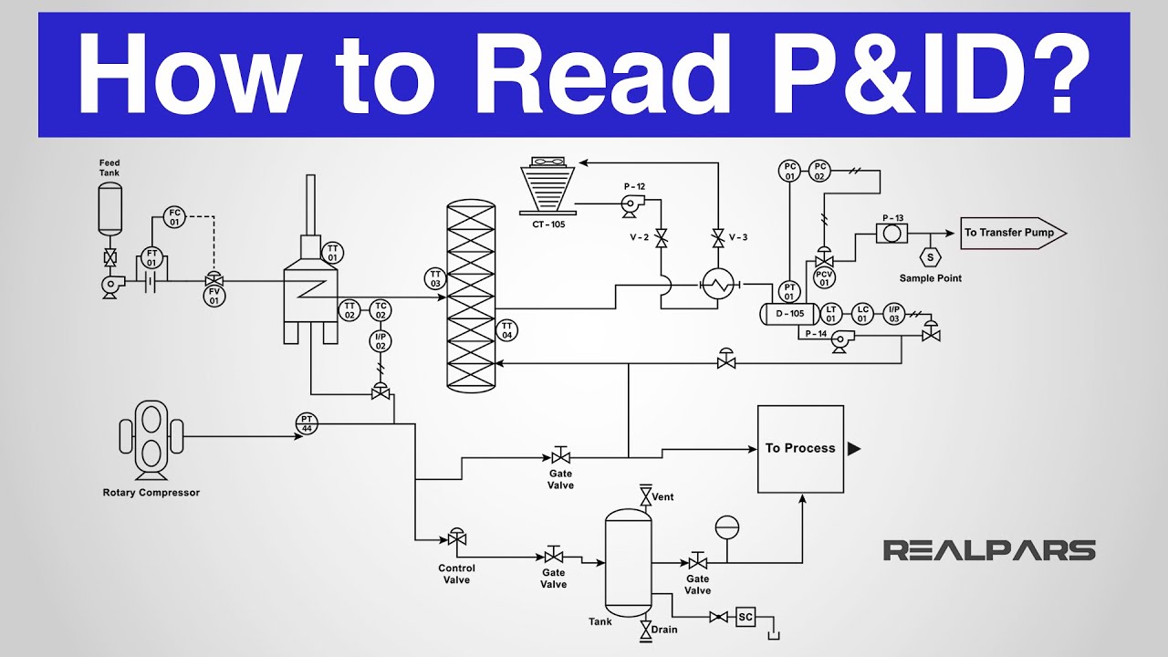
A Process and Instrumentation Diagram (P & ID) shows the process flow and interconnection of process equipment which is used control a process. The P & ID includes every mechanical aspect of the plant except stream flows, pipe routing, pipe lengths, pipe fittings, supports, structure & foundations.
P&ID Symbols and Notation Lucidchart
P&IDs are a schematic illustration of the functional relationship of piping, instrumentation and system equipment components used in the field of instrumentation and control or automation. They are typically created by engineers who are designing a manufacturing process for a physical plant.
What is P and ID Diagram? EXCEL
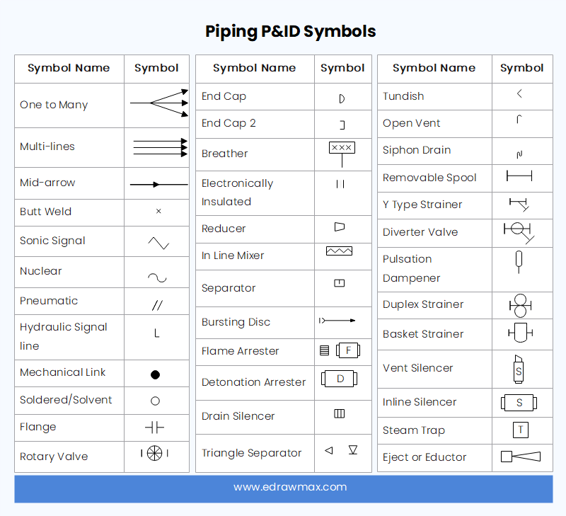
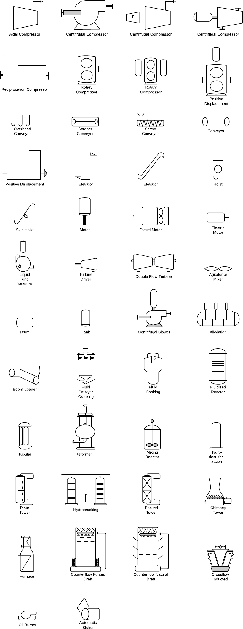
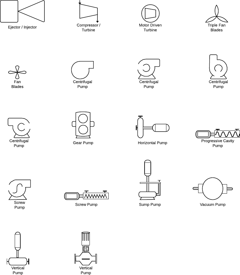
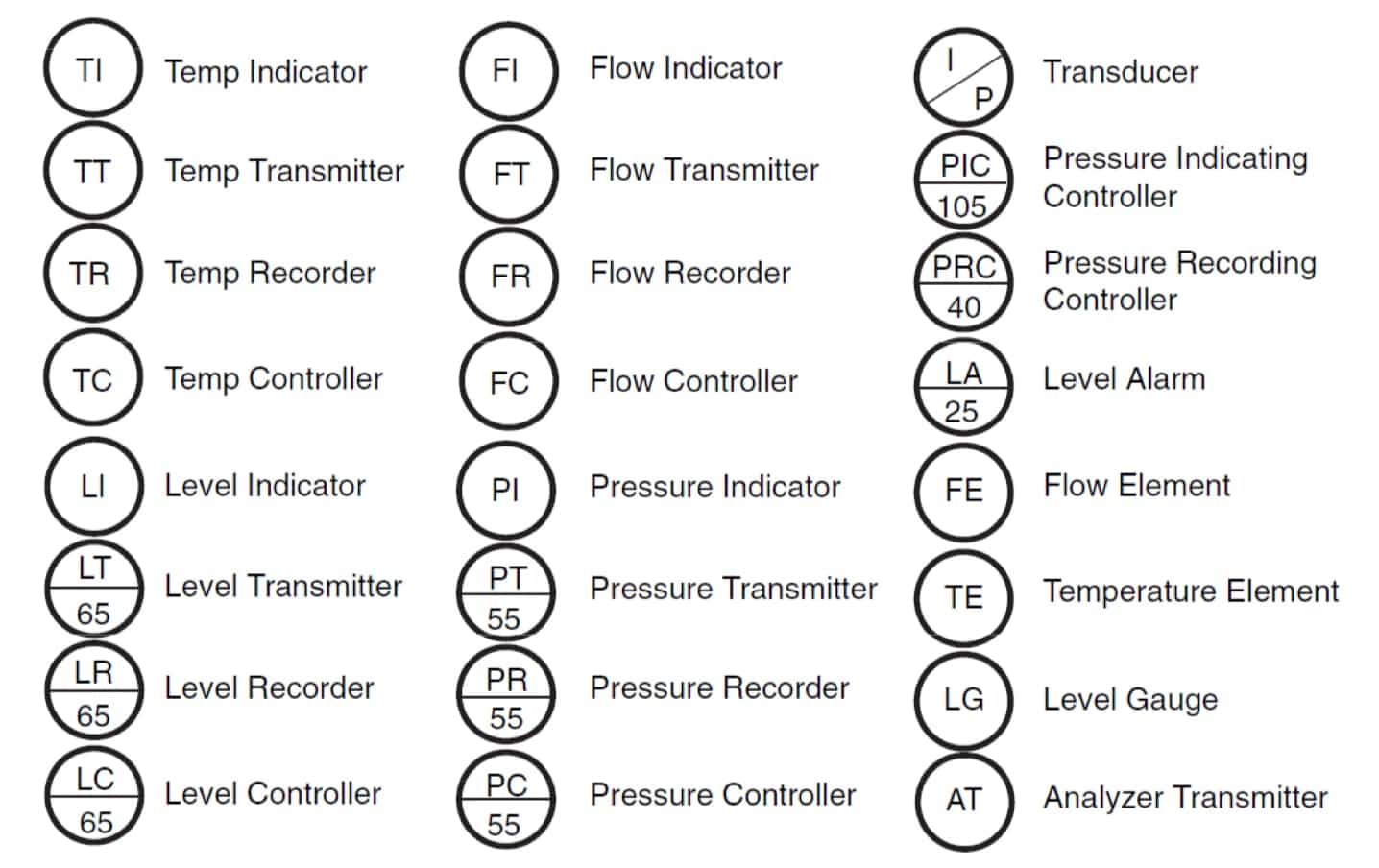
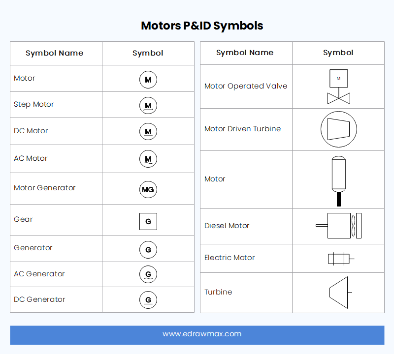
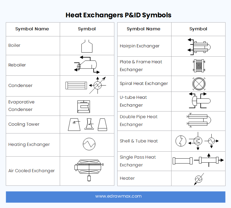
Piping and Instrument Diagram Standard Symbols Detailed Documentation provides a standard set of shapes & symbols for documenting P&ID and PFD, including standard shapes of instrument, valves, pump, heating exchanges, mixers, crushers, vessels, compressors, filters, motors and connecting shapes. Or Gate Not Gate Correcting Element Diamond
P&ID Symbol Diagram Basics 3/3 Functional Identification and Naming Conventions (2022)
The PID-controller output will be a combination of the P-only, I-only and D-only controller outputs. Analogous to the P-controller output for the step input, the P-controller output for the pulse input will exactly resemble the input. Figure 9. P-controller output for pulse input. The I-controller output represents the area under the input graph.
How to Read a P&ID? (Piping & Instrumentation Diagram) YouTube
A piping and instrumentation diagram (P&ID) is defined as follows: A diagram which shows the interconnection of process equipment and the instrumentation used to control the process. In the process industry, a standard set of symbols is used to prepare drawings of processes.
P&ID Symbols and Meanings EdrawMax Online
A proportional-integral-derivative controller ( PID controller or three-term controller) is a control loop mechanism employing feedback that is widely used in industrial control systems and a variety of other applications requiring continuously modulated control.

P & ID Diagram. How To Read P&ID Drawing Easily. Piping & Instrumentation Diagram Explained
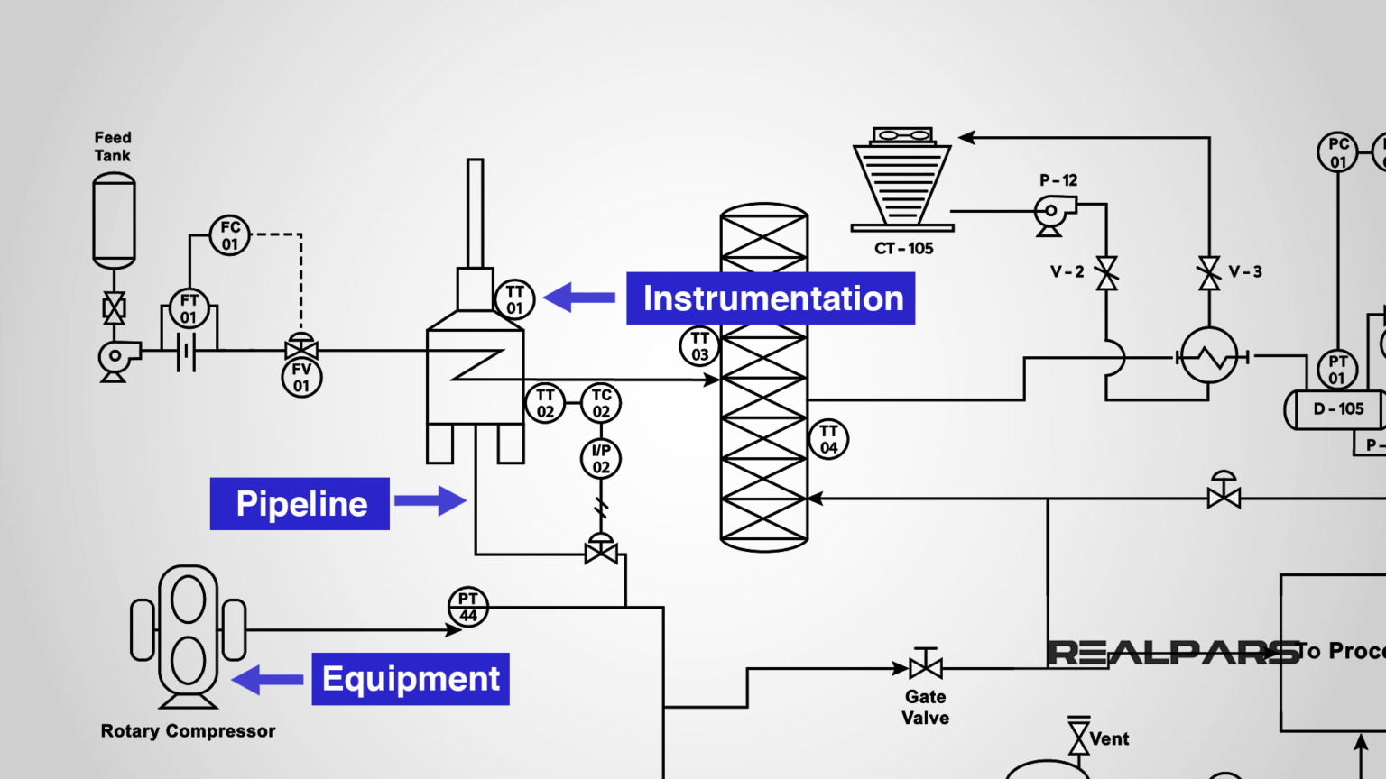
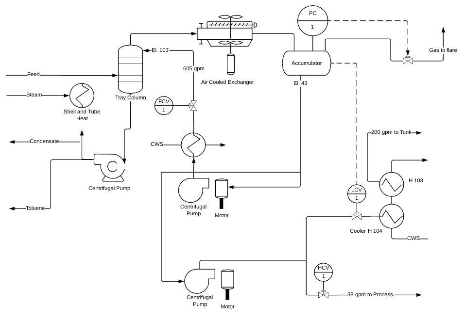
A piping and instrumentation diagram displays the piping components (for example equipment, valves, reducers and so on) of an actual physical process flow and is often used in the engineering projects, such as setting up steam boilers, heat exchangers, electric boilers and more. To read a piping and instrumentation diagram, simply break down.
Instrumentation Today HOW TO READ A P&ID
The P&ID's are used to operate process systems. P&ID Diagram - Online Drawing Tool A P&ID should include: Instrumentation and designations Mechanical equipment with names and numbers All valves and their identifications Process piping, sizes and identification

P&ID Document Reading Example Instrumentation Tools
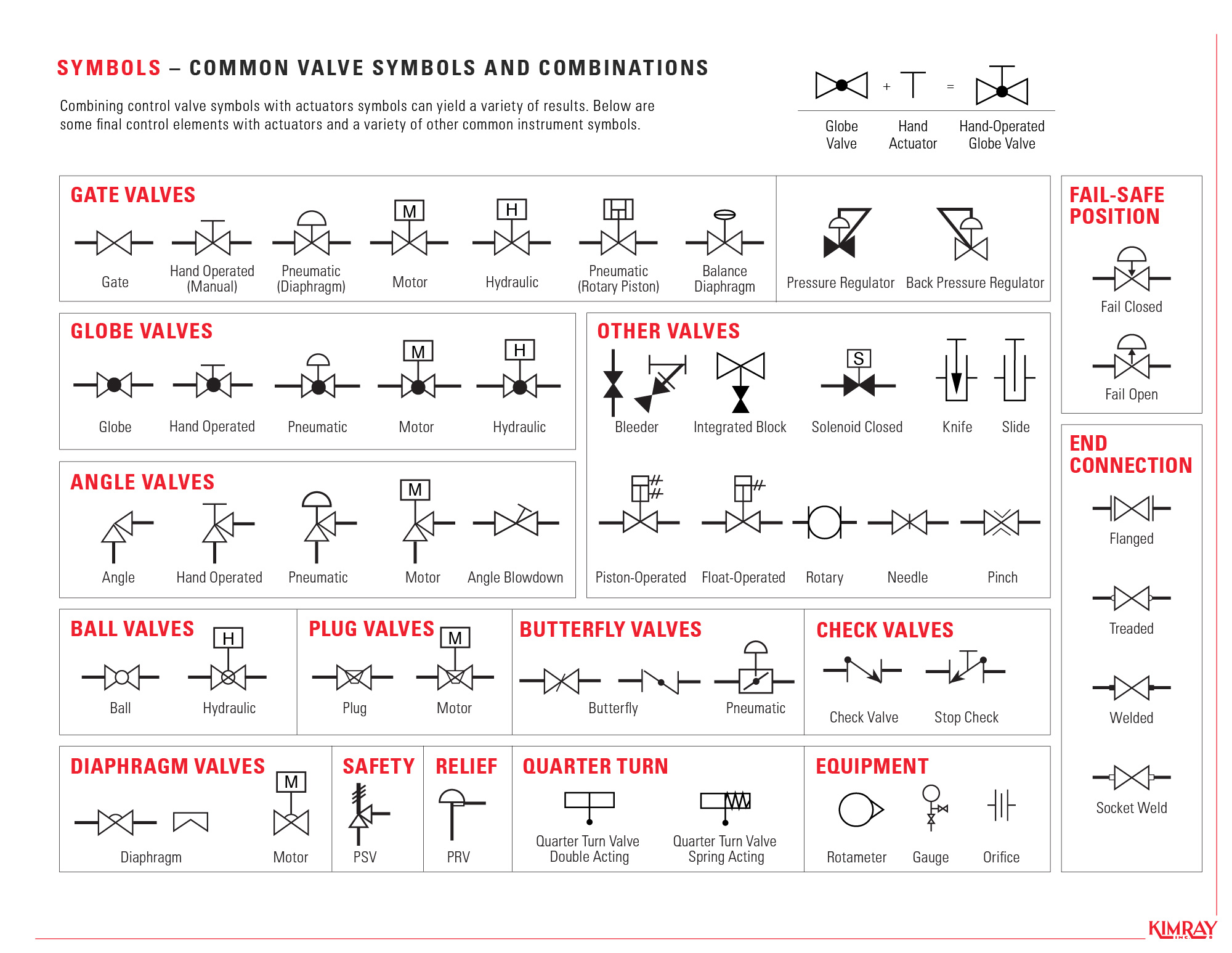
Piping and Instrumentation Diagrams (P&IDs) use specific symbols to show the connectivity of equipment, sensors, and valves in a control system. These symbols can represent actuators, sensors, and controllers and may be apparent in most, if not all, system diagrams. P&IDs provide more detail than a process flow diagram with the exception of the.
Instrumentation Today HOW TO READ A P&ID
1. What is P&ID? Abbreviated as P&ID, a piping and instrumentation diagram is an articulate drawing of a processing plan that entails the piping and process equipment with its instrumentation and control machinery. It displays the piping and associated parts of a physical process flow. Such diagrams are famous in the engineering field.
P&ID Symbols and Meanings EdrawMax Online
P&IDs, or Piping and Instrumentation Diagrams to give them their full name, are schematic representations of pipelines, equipment, instrumentation, and control systems found in process environments such as Oil Refineries, Chemical Plants, Paper Mills, and Cement Plants, etc. P&ID Symbols and Codes
How to Read Oil and Gas P&ID Symbols Kimray
December 21, 2017. A piping and instrumentation diagram (P&ID) is a graphic representation of a process system that includes the piping, vessels, control valves, instrumentation, and other process components and equipment in the system. The P&ID is the primary schematic drawing used for laying out a process control system's installation.
Qué es un P&ID Guía para principiantes
The P&ID diagram software comes with a rich set of high-quality P&ID symbols for you to create different kinds of P&ID diagrams. Without a doubt, Visual Paradigm Online is the best P&ID software to create schematics for the process industry. With Visual Paradigm Online, you don't need to start each P&ID from scratch because a rich set of piping.
